
BMW X5: BMW Gesture Control
Principle
Several iDrive functions can be operated by hand motion using BMW Gesture Control.
Overview
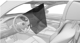
The camera in the headliner detects gestures that are carried out in the area of the center console at the height of the Control Display.
Activate/deactivate
1. "CAR".
2. "Settings".
3. "General settings".
4. "Gesture control".
5. "Gesture control".
Carrying out gestures
- Perform gestures underneath the interior mirror and next to the steering wheel.
- Execute gestures clearly.
- The gestures can also be executed from the front-passenger side.
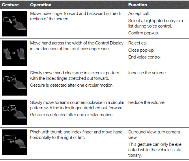
Possible gestures
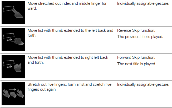
Assigning gesture individually
General information
Two gestures can be assigned individually and can be configured for certain functions, such as:
- Destination guidance to home address.
- Mute/Playback
- Control Display on/off
Select function
1. "CAR".
2. "Settings".
3. "General settings".
4. "Gesture control".
5. "Function assignment gesture 1" or "Function assignment gesture 2".
6. Select the desired setting.
System limits
Gesture recognition by the camera in the headliner can be disturbed by the following circumstances:
- The camera lens is covered.
- Objects are located on the interior mirror.
- The camera lens is dirty, clean camera lens.
Sensors and camera lenses.
- The gesture is executed outside of the detection range.
- Wearing of gloves or jewelry.
READ NEXT:
 Principle
Remote Software Upgrade can be used to update
the entire software of the vehicle. This
makes new functions, functional enhancements
or quality improvements available.
General information
BMW recommend
Search for an upgrade
Standby must be turned on to search for a software
upgrade.
Automatic search
The vehicle regularly searches for updates in the
background.
Manual search
1. "CAR".
2. "Settings".
3. "General settings
SEE MORE:
Stabilizer Bar
REMOVING AND INSTALLING/REPLACING REAR STABILIZER
Necessary preliminary tasks:
Remove both stabilizer links from stabilizer.
Release screws (1).
Replacement only: Remove both rubber mounts from stabilizer.
Turn stabilizer (2) and remove sideways.
Installation:
Check both rubber mounts for damage
Starter Lead
REMOVING AND INSTALLING OR REPLACING BATTERY POSITIVE LEAD
(BETWEEN ALTERNATOR, STARTER MOTOR AND JUMP START CONNECTION POINT) (N62,
N62TU)
REFERENCE CHART
REMOVING AND INSTALLING OR REPLACING BATTERY POSITIVE LEAD
(BETWEEN ALTERNATOR, STARTER AND BATTERY POSITIVE TERMINAL) (N62)
REFERENCE CHART (N
